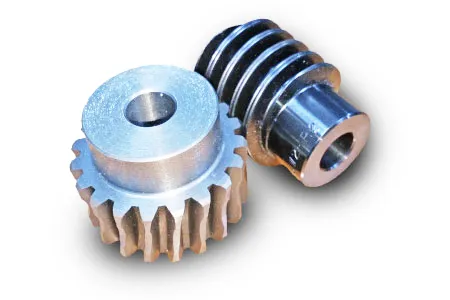
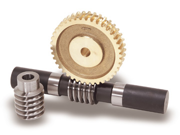
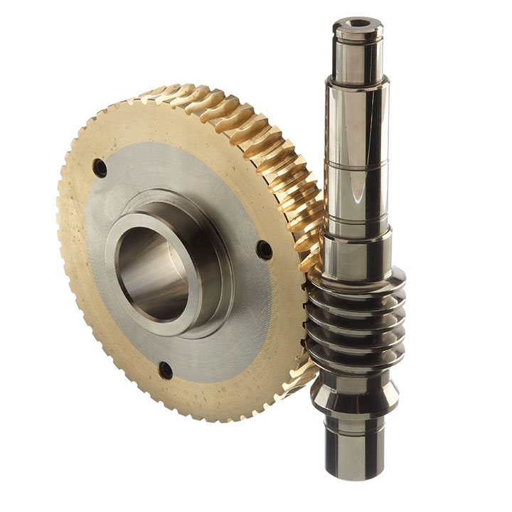
Product Description
Product Description
|
Products |
Gear |
|||
|
Module |
M0.3-M10 |
|||
|
Precision grade |
DIN5, DIN6, DIN7, DIN8, DIN10 |
|||
|
Pressure angle: |
14.5 degree, 15 degree, 20 degree |
|||
|
Material |
C45 steel, ,304SS, 316SS, 20CrMo,40Cr, brass, nylon, POM, and so on |
|||
|
Heat treatment |
Hardening and Tempering High Frequency Quenching Carburization etc |
|||
|
Surface treatment |
Blacking, Polishing, Anodization, Chrome Plating, Zinc Plating, Nickel Plating |
|||
|
Application |
Precision cutting machines.Lathes machine |
|||
|
Machining process: |
CNC engine latheCNC milling machine |
|||
Detailed Photos
Test
Inspection steps before delivery: Use GO/Nogo inspect hole—Use micrometer check dimensions—Next use stiffness detection system inspect hardness–Finally use CMM inspect precision
Packaging & Shipping
Company Profile
ZheJiang Haorongshengye Electrical Equipment Co., Ltd.
1. Was founded in 2008
2. Our Principle:
“Credibility Supremacy, and Customer First”
3. Our Promise:
“High quality products, and Excellent Service”
4. Our Value:
“Being Honesty, Doing the Best, and Long-lasting Development”
5. Our Aim:
“Develop to be a leader in the power transmission parts industry in the world”
|
6.Our services: |
1).Competitive price |
|||
|
2).High quality products |
||||
|
3).OEM service or can customized according to your drawings |
||||
|
4).Reply your inquiry in 24 hours |
||||
|
5).Professional technical team 24 hours online service |
||||
|
6).Provide sample service |
||||
Main products
Machines
Exbihition
| Application: | Machinery |
|---|---|
| Hardness: | Hardened Tooth Surface |
| Gear Position: | Internal Gear |
| Manufacturing Method: | Hobbing |
| Toothed Portion Shape: | Spur Gear |
| Material: | Steel |
| Samples: |
US$ 200/Piece
1 Piece(Min.Order) | |
|---|
| Customization: |
Available
| Customized Request |
|---|
Can you provide examples of machinery that use worm gears?
Worm gears are utilized in various machinery and mechanical systems where precise motion control, high gear reduction ratios, and self-locking capabilities are required. Here are some examples of machinery that commonly use worm gears:
- Elevators: Worm gears are commonly employed in elevator systems to control the vertical movement of the elevator car. The high gear reduction ratio provided by worm gears allows for smooth and controlled lifting and lowering of heavy loads.
- Conveyor systems: Worm gears are used in conveyor systems to drive the movement of belts or chains. The self-locking nature of worm gears helps prevent the conveyor from back-driving when the power is turned off, ensuring that the materials or products being transported stay in place.
- Automotive applications: Worm gears can be found in automotive steering systems. They are often used in the steering gearboxes to convert the rotational motion of the steering wheel into lateral movement of the vehicle’s wheels. Worm gears provide mechanical advantage and precise control for steering operations.
- Milling machines: Worm gears are utilized in milling machines to control the movement of the worktable or the spindle. They offer high torque transmission and accurate positioning, facilitating precise cutting and shaping of materials during milling operations.
- Lifts and hoists: Worm gears are commonly employed in lifting and hoisting equipment, such as cranes and winches. Their high gear reduction ratio allows for the lifting of heavy loads with minimal effort, while the self-locking property prevents the load from descending unintentionally.
- Rotary actuators: Worm gears are used in rotary actuators to convert linear motion into rotary motion. They are employed in various applications, including valve actuators, robotic arms, and indexing mechanisms, where controlled and precise rotational movement is required.
- Packaging machinery: Worm gears find application in packaging machinery, such as filling machines and capping machines. They assist in controlling the movement of conveyor belts, rotating discs, or cam mechanisms, enabling accurate and synchronized packaging operations.
- Printing presses: Worm gears are utilized in printing presses to control the paper feed and the movement of the printing plates. They provide precise and consistent motion, ensuring accurate registration and alignment of the printed images.
These are just a few examples, and worm gears can be found in many other applications, including machine tools, textile machinery, food processing equipment, and more. The unique characteristics of worm gears make them suitable for various industries where motion control, high torque transmission, and self-locking capabilities are essential.
Can worm gears be used in both horizontal and vertical orientations?
Yes, worm gears can be used in both horizontal and vertical orientations. Here’s a detailed explanation of the suitability of worm gears for different orientations:
1. Horizontal Orientation: Worm gears are commonly used in horizontal orientations and are well-suited for such applications. In a horizontal configuration, the worm gear’s weight is primarily supported by the bearings and housing. The lubrication and load-carrying capabilities of the gear design are optimized for horizontal operation, allowing for efficient power transmission and torque generation. Horizontal worm gear applications include conveyor systems, mixers, mills, and many other industrial machinery setups.
2. Vertical Orientation: Worm gears can also be used in vertical orientations, although there are some additional considerations to address in such cases. In a vertical configuration, the weight of the worm gear exerts an axial force on the worm shaft, which can introduce additional load and affect the gear’s performance. To ensure proper operation in a vertical orientation, the following factors should be considered:
- Thrust load handling: Vertical orientations impose a thrust load on the worm gear due to the weight of the gear and any additional external loads. The gear design should be capable of handling and transmitting this thrust load without excessive wear or deformation. Proper bearing selection and lubrication are crucial to support the axial load and maintain optimal performance.
- Lubrication: Lubrication becomes even more critical in vertical worm gear applications. Adequate lubrication ensures proper lubricant film formation to minimize friction, reduce wear, and dissipate heat generated during operation. Careful consideration should be given to the lubricant type, viscosity, and lubrication method to ensure effective lubrication, particularly in the upper parts of the gear where lubricant distribution may be more challenging.
- Backlash control: In vertical orientations, gravity can cause the load to act on the gear in the opposite direction, potentially leading to increased backlash. Proper gear design, including tooth geometry and clearance adjustments, can help minimize backlash and ensure precise motion control and positional stability.
- Bearing selection: The choice of bearings becomes crucial in vertical worm gear applications. Thrust bearings or combinations of thrust and radial bearings may be required to handle the axial and radial loads effectively. Bearings with appropriate load-carrying capacities and stiffness are selected to ensure smooth operation and minimize deflection under vertical loads.
- Sealing: Vertical orientations may require additional sealing measures to prevent lubricant leakage and ingress of contaminants. Proper sealing and protection mechanisms, such as seals or gaskets, should be implemented to maintain the integrity of the gear system and ensure reliable operation.
In summary, worm gears can be utilized in both horizontal and vertical orientations. However, certain considerations related to thrust load handling, lubrication, backlash control, bearing selection, and sealing should be taken into account for vertical applications. By addressing these factors appropriately, worm gears can effectively transmit power and torque, whether in horizontal or vertical configurations.
How do you calculate the gear ratio of a worm gear?
Calculating the gear ratio of a worm gear involves determining the number of teeth on the worm wheel and the pitch diameter of both the worm and worm wheel. Here’s the step-by-step process:
- Determine the number of teeth on the worm wheel (Zworm wheel). This information can usually be obtained from the gear specifications or by physically counting the teeth.
- Measure or determine the pitch diameter of the worm (Dworm) and the worm wheel (Dworm wheel). The pitch diameter is the diameter of the reference circle that corresponds to the pitch of the gear. It can be measured directly or calculated using the formula: Dpitch = (Z / P), where Z is the number of teeth and P is the circular pitch (the distance between corresponding points on adjacent teeth).
- Calculate the gear ratio (GR) using the following formula: GR = (Zworm wheel / Zworm) * (Dworm wheel / Dworm).
The gear ratio represents the speed reduction and torque multiplication provided by the worm gear system. A higher gear ratio indicates a greater reduction in speed and higher torque output, while a lower gear ratio results in less speed reduction and lower torque output.
It’s worth noting that in worm gear systems, the gear ratio is also influenced by the helix angle and lead angle of the worm. These angles determine the rate of rotation and axial movement per revolution of the worm. Therefore, when selecting a worm gear, it’s important to consider not only the gear ratio but also the specific design parameters and performance characteristics of the worm and worm wheel.
editor by CX 2023-10-04


